Applications

Versatile ERS Applications for Reliable Power Transmission.

Emergency Restoration Systems (ERS) provide utilities with a versatile solution for maintaining transmission continuity across a wide range of operational scenarios. From emergency restoration and planned maintenance to tower replacement, substation expansion, grid modernization, disaster recovery, and temporary bypass installations, ERS enables rapid deployment, minimizes outages, enhances grid resilience, and ensures reliable power delivery with engineered precision and operational flexibility.

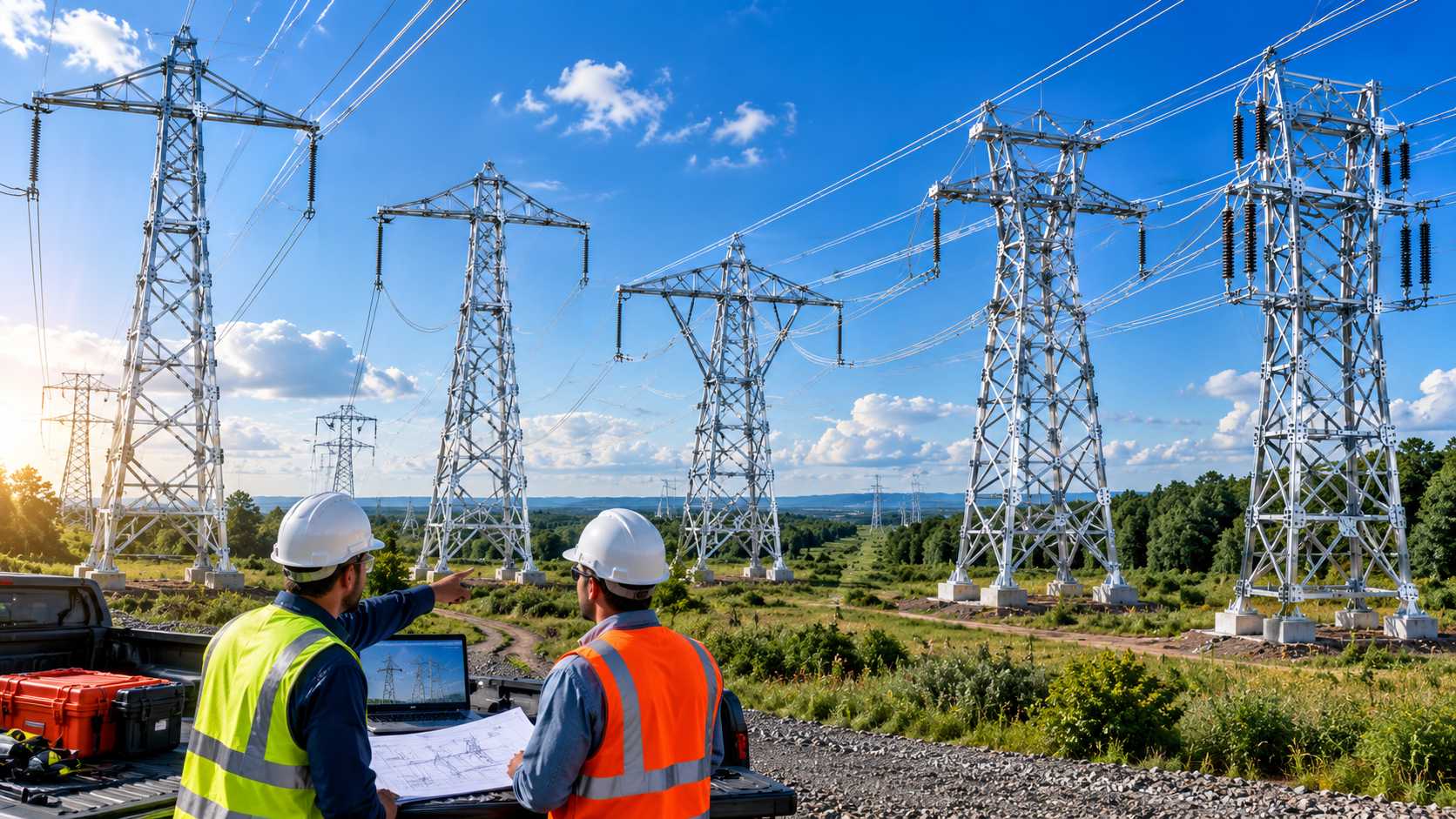
Emergency Restoration

Rapid power restoration after storms, failures, and emergency outages.

Planned Maintenance

Maintain transmission continuity during upgrades and scheduled work.

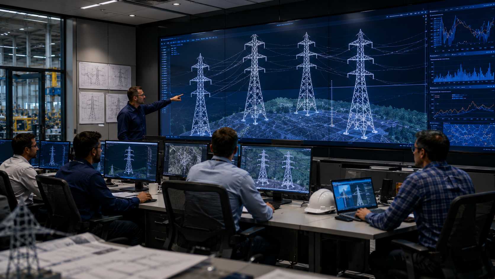
Grid Modernization

Support network expansion and modern transmission infrastructure.

Versatile ERS Applications for Reliable Transmission

Emergency Restoration Systems provide electric power utilities with engineered modular towers to maintain line continuity across critical operational and emergency scenarios.

01
01 / 06

Emergency Restoration

Rapid deployment of modular temporary structures to restore power continuity following storms, natural disasters, ice events, or catastrophic tower collapses.

02
02 / 06

Planned Maintenance

Ensures uninterrupted power transmission during scheduled grid servicing, insulator replacements, tower repairs, and high-capacity conductor stringing.

03
03 / 06

Temporary Bypass Lines

Creates temporary high-voltage diversions around highway expansions, river crossings, railway construction, and urban infrastructure developments.

04
04 / 06

Substation Expansion

Provides temporary gantry and line bypasses into substations during bay additions, busbar maintenance, transformer swaps, and switchgear overhauls.

05
05 / 06

Grid Modernization

Supports voltage uprating initiatives and connects renewable solar/wind generation plants to the primary grid without regional load shedding.

06
06 / 06

Disaster Preparedness

Enables electric utilities to pre-position modular tower inventory in strategic stockpiles for immediate turnkey emergency mobilization when crises strike.

How Utilities Use ERS Solutions

ERS systems support utilities across two primary operational contexts — emergency restoration and planned maintenance — each with distinct requirements and deployment approaches.

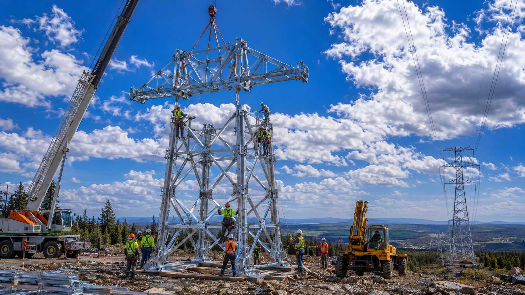
Emergency Restoration — ERS Tower Deployment
01
Emergency Restoration

Tower Collapse Recovery

Support rapid transmission restoration following storm damage, flooding, structural failures, conflict-related damage, and cascading tower collapse events — minimising outage duration and restoring grid continuity.

  • Cyclone and storm event recovery
  • Flood-related tower failure response
  • Cascading tower collapse restoration
  • Conflict and emergency infrastructure recovery
Explore Recovery Solutions
Planned Operations

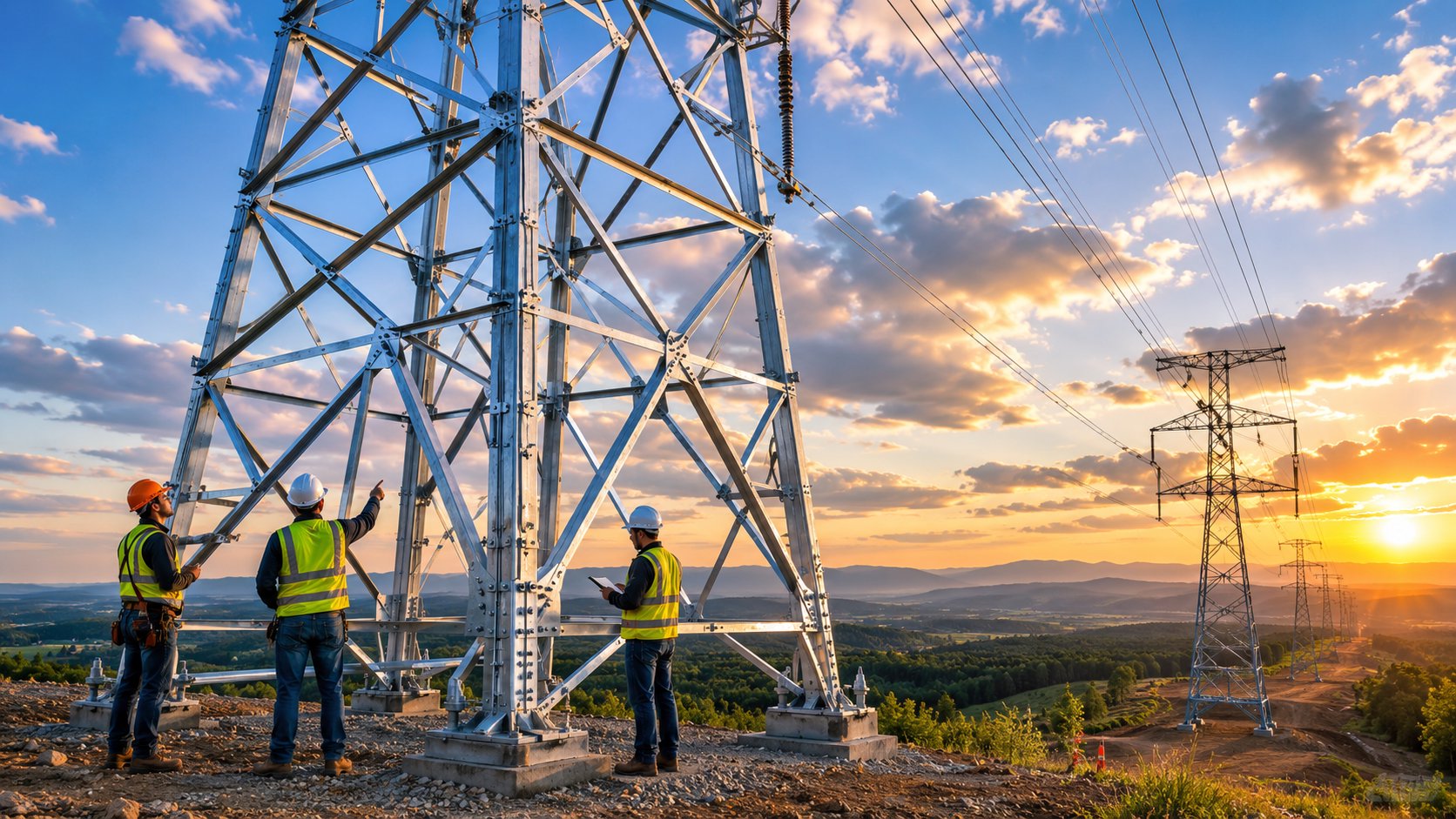
Planned Maintenance

Maintain transmission continuity during planned maintenance activities, reconductoring programmes, network upgrades, and infrastructure modernisation projects — eliminating forced outages during operational activities.

  • Reconductoring and line upgrade projects
  • Tower replacement and structural maintenance
  • Asset life extension programmes
  • Network expansion and grid modernisation
Explore Maintenance Solutions
Planned Maintenance — ERS Tower Operations
02

Navigate the Supply Ecosystem

Explore complete ERS supply solutions—from manufacturing to installation and support.

Why Industry Trusts Hi-Tech

Reliable manufacturing for critical transmission projects.

Frequently Asked Questions

Everything you need to know about HiTech ERS solutions, capabilities, and standards.

What are the different ERS tower configurations?

Hi-Tech ERS towers are available in five configurations: Suspension (for straight routes), Running Angle (for directional changes), Dead-End/Tension (for high-load termination and crossings), Herringbone (twin-mast multi-circuit), and Chainette (portal-style wide corridor). Each is engineered for a specific functional role within a transmission corridor.

A Suspension configuration supports conductors on straight or near-straight transmission sections where conductor loads are balanced transversely. It is the most common ERS configuration used for emergency bypass lines, reconductoring corridors, and temporary restoration routes along straight alignments.

A Running Angle configuration is used where the transmission line changes direction — at deviation angles typically between 2° and 30°. The cross arm and structure are designed to handle the resultant horizontal conductor load created by the change in line direction, making it suitable for route diversions and corridor adjustments.

A Dead-End or Tension configuration is required wherever the full longitudinal conductor tension must be transferred to the structure — at line terminations, river crossings, long spans, section boundaries, and critical restoration anchor points. These structures are significantly more robust than suspension types and are typically guyed for additional stability.

The Herringbone is a twin-mast ERS arrangement where two vertical masts are connected by cross-bracing in a herringbone pattern. This configuration provides significantly increased structural capacity, making it suitable for multi-circuit systems, heavy-duty restoration projects, and complex loading conditions that exceed the capacity of single-mast configurations.

The Chainette is a portal-style ERS structure designed for wider transmission corridors and special crossing requirements. Its wide base and horizontal top beam allow it to span greater widths than conventional mast configurations, making it the configuration of choice for portal structure replacements and wide corridor crossings.

Yes — in fact, most ERS restoration routes use multiple configurations. A typical route will use Dead-End configurations at each terminal, Suspension configurations across straight sections, and Running Angle configurations wherever the route changes direction. Configuration selection is performed section-by-section based on the engineering requirements at each location.

Configuration selection follows a structured engineering evaluation covering route geometry, tower function, conductor loading, span length, circuit arrangement, voltage level, weather loads, foundation conditions, and access constraints. Hi-Tech's engineering team performs this evaluation for each project to ensure the deployed configuration matches the specific requirements of the transmission corridor.

River crossings require Dead-End/Tension configurations on both banks of the crossing. The dead-end structures anchor the long span conductors across the water body, absorbing the full longitudinal tension generated by the extended span. Suspension towers on either side of the dead-ends carry the normal balanced loads on the approach sections.

Yes. All five Hi-Tech ERS configurations — Suspension, Running Angle, Dead-End/Tension, Herringbone, and Chainette — are available for deployment on systems from 33kV through to 800kV, including 400kV EHV and 765kV UHV corridors. Configuration dimensions, structural capacities, and insulator string arrangements are engineered to suit the specific voltage class requirements.