Straight Transmission Route
Recommended Configuration
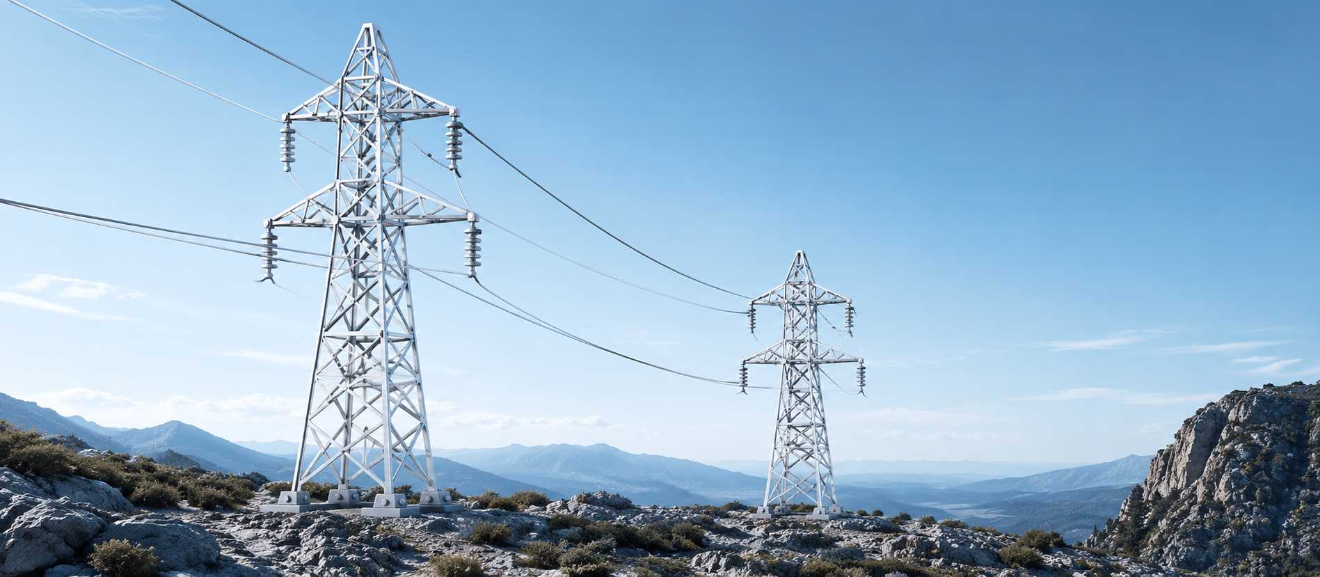
SuspensionOur ERS configuration solutions are engineered to match diverse transmission challenges with precision and flexibility. From suspension and tension arrangements to angle, terminal, and special configurations, every system is evaluated to meet site conditions, voltage levels, loading requirements, and restoration objectives. This ensures faster deployment, structural reliability, and optimized field performance for every project.

Optimized ERS layouts engineered for every transmission requirement.

Adaptable configurations for varied terrain, voltage, and loading needs.
Customized ERS configurations for efficient and reliable deployment.
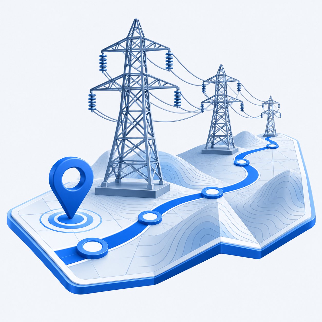
Different sections of a transmission network perform different functions. Configuration selection follows a structured engineering evaluation — from route geometry through to voltage and circuit requirements.
Route Geometry
Tower Function
Loading Condition
Circuit Requirement
Voltage Level
Complete ERS configuration range for every transmission requirement.
Supports balanced conductor loading on straight transmission sections. The standard configuration for linear route restoration and bypass projects.
Applications
Accommodates route deviations and directional changes where the transmission line must deviate from a straight alignment.
Applications
Supports high longitudinal conductor loads and termination points. Required for river crossings, long spans, critical restoration anchor locations.
Applications
Twin-mast ERS arrangement designed for multi-circuit restoration and specialised heavy-duty loading conditions across complex corridors.
Applications
Portal-style structure supporting wider transmission corridors where standard mast configurations cannot be deployed.
Applications
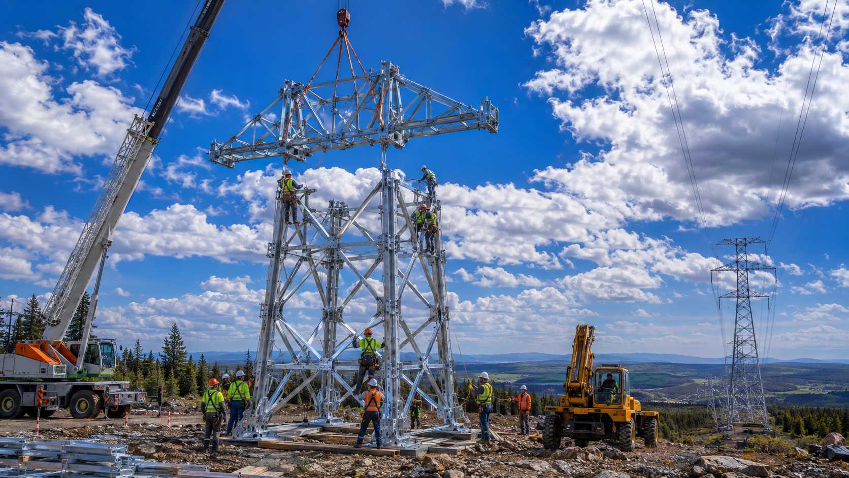
ERS configurations are engineered to replicate the functional role of conventional transmission towers during restoration and temporary transmission applications.
| Conventional Tower Function | Suspension | Running Angle | Dead-End / Tension | Herringbone | Chainette |
|---|---|---|---|---|---|
| Suspension Tower | |||||
| Tangent Tower | |||||
| Angle Tower | |||||
| Tension Tower | |||||
| Dead-End Tower | |||||
| Multi-Circuit Tower | |||||
| Portal Structure |
Suspension Tower
2 matching configurations
Tangent Tower
2 matching configurations
Angle Tower
2 matching configurations
Tension Tower
2 matching configurations
Dead-End Tower
2 matching configurations
Multi-Circuit Tower
2 matching configurations
Portal Structure
1 matching configuration
Select the right ERS configuration for your specific transmission application.
Recommended Configuration
SuspensionRecommended Configuration
Running AngleRecommended Configuration
Dead-End / TensionRecommended Configuration
HerringboneRecommended Configuration
ChainetteRecommended Configuration
Combination of ConfigurationsMost restoration projects combine multiple ERS configurations to accommodate route geometry, conductor loading, terrain conditions, and operational requirements.
Swipe to explore the full route →
Dead-End
Terminal / Anchor
Suspension
Straight Section
Suspension
Straight Section
Running Angle
Direction Change
Suspension
Straight Section
Dead-End
Terminal / Anchor
This example shows a typical ERS restoration route — anchored by Dead-End configurations at each terminal, with Suspension configurations covering straight-line sections and a Running Angle configuration managing the directional change at mid-route.
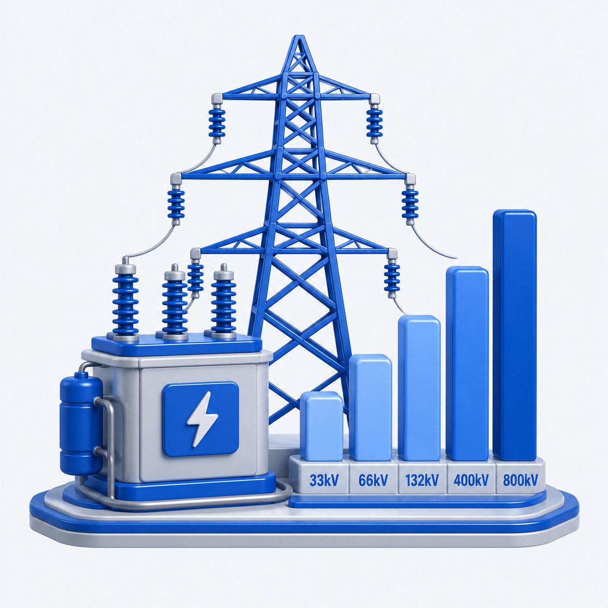
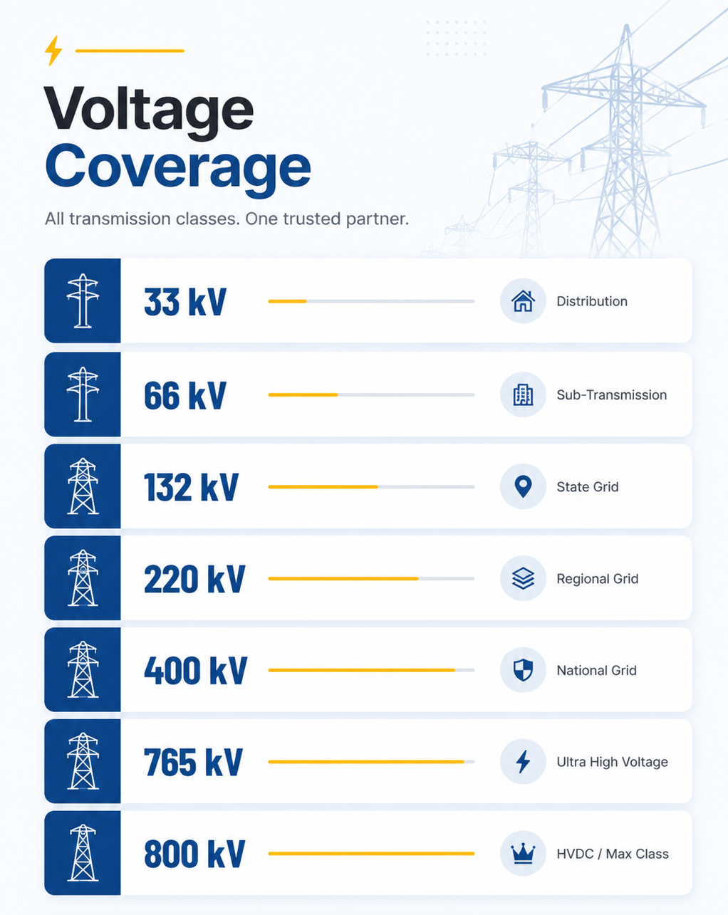
Every Hi-Tech ERS configuration is engineered to perform across the complete transmission voltage spectrum—from 33kV distribution networks to 800kV HVDC corridors. Designed for diverse transmission applications, each configuration supports reliable restoration, planned maintenance, temporary bypass, and reconductoring projects while maintaining proven structural performance and engineering reliability.
Key engineering factors that determine the optimal ERS configuration for each transmission project.

Alignment and route angles determine the ideal ERS configuration for each corridor.

Terrain and crossing conditions influence span design and configuration selection.

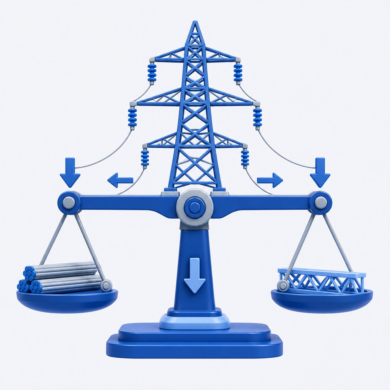
Conductor loads determine the most suitable structural ERS configuration design.
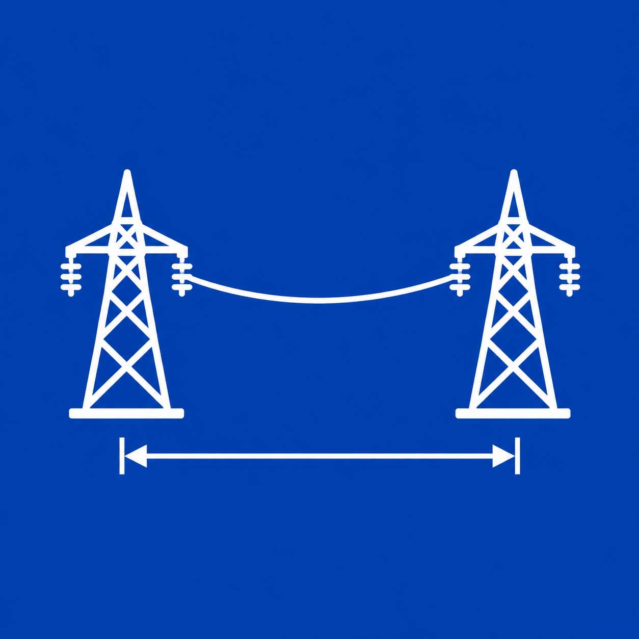
Longer spans require stronger configurations to control conductor tension and sag.
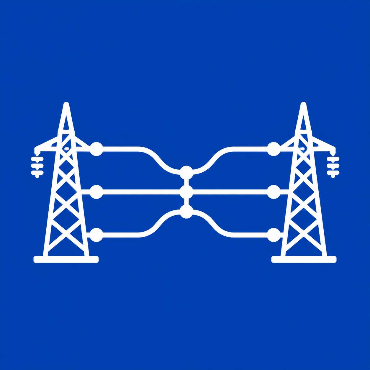
Circuit requirements define the appropriate ERS configuration for each application.
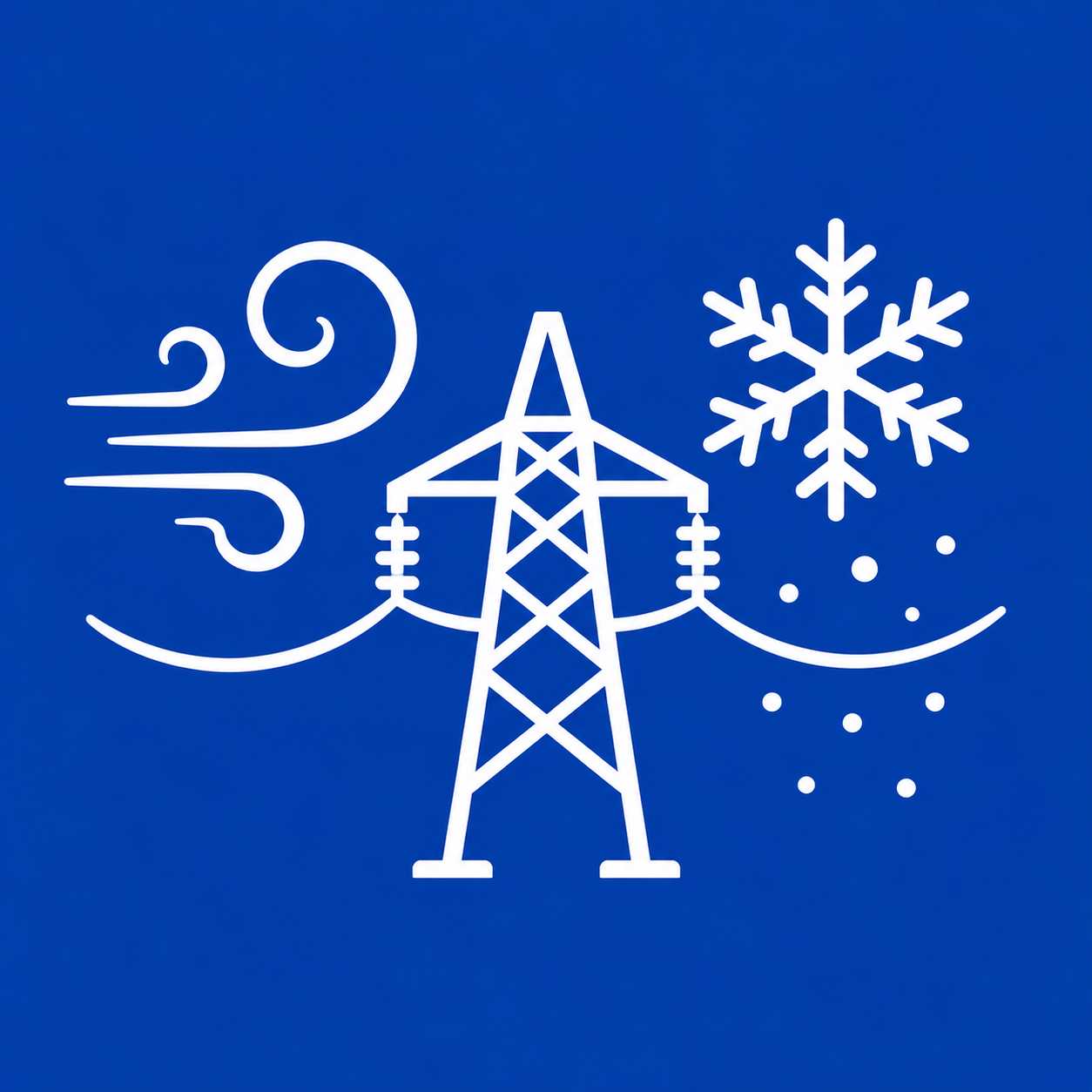
Wind, ice, and thermal loads influence structural design and configuration choice.

Ground strength and soil conditions determine foundation and tower selection needs.
Site access limitations influence deployment strategy and configuration selection.
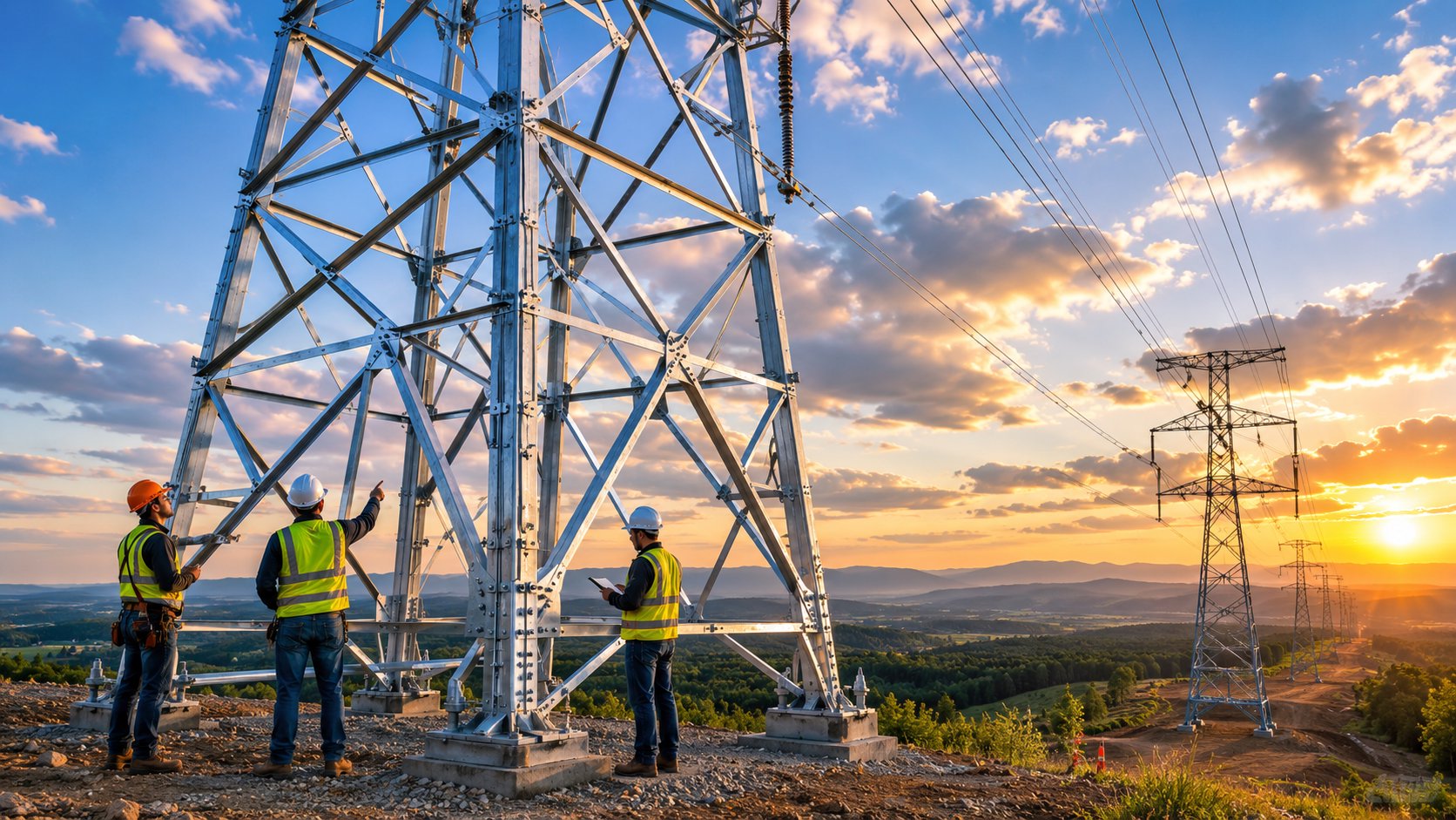
Explore complete ERS supply solutions—from manufacturing to installation and support.
Complete ERS tower solutions engineered for rapid deployment, reliable restoration, and long-term grid resilience.
Choose modular ERS configurations including suspension, tension, angle, dead-end, and custom tower solutions.
Precision-built ERS towers using certified materials, advanced fabrication, and strict international quality standards.
Professional installation support ensuring safe deployment, efficient erection, and dependable system commissioning.
Comprehensive ERS training, planning software, and field guidance for confident deployment and operation.
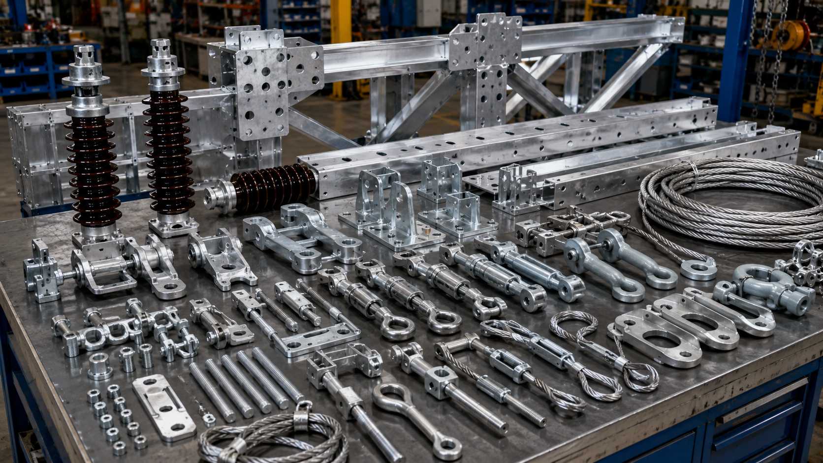
Certified ERS hardware, insulators, anchors, connectors, and accessories for dependable field performance.
Protecting the infrastructure that powers homes, industries, and nations.
Initial evaluation of project scope, timeline requirements, and operational objectives for the transmission restoration or bypass project.
Survey and analysis of the transmission corridor — route geometry, deviation angles, terrain, and crossing requirements.
Structural and conductor loading calculations — longitudinal tensions, wind loads, span lengths, and circuit configuration requirements.
Selection of appropriate ERS configurations for each route section — suspension, angle, dead-end, herringbone, or chainette as required.
Structural calculations and design verification against applicable standards including IEEE 1070, IS:802, and project-specific loading.
Finalisation of erection sequence, logistics, foundation design, and site-specific installation methodology for each configuration type.
Reliable manufacturing for critical transmission projects.

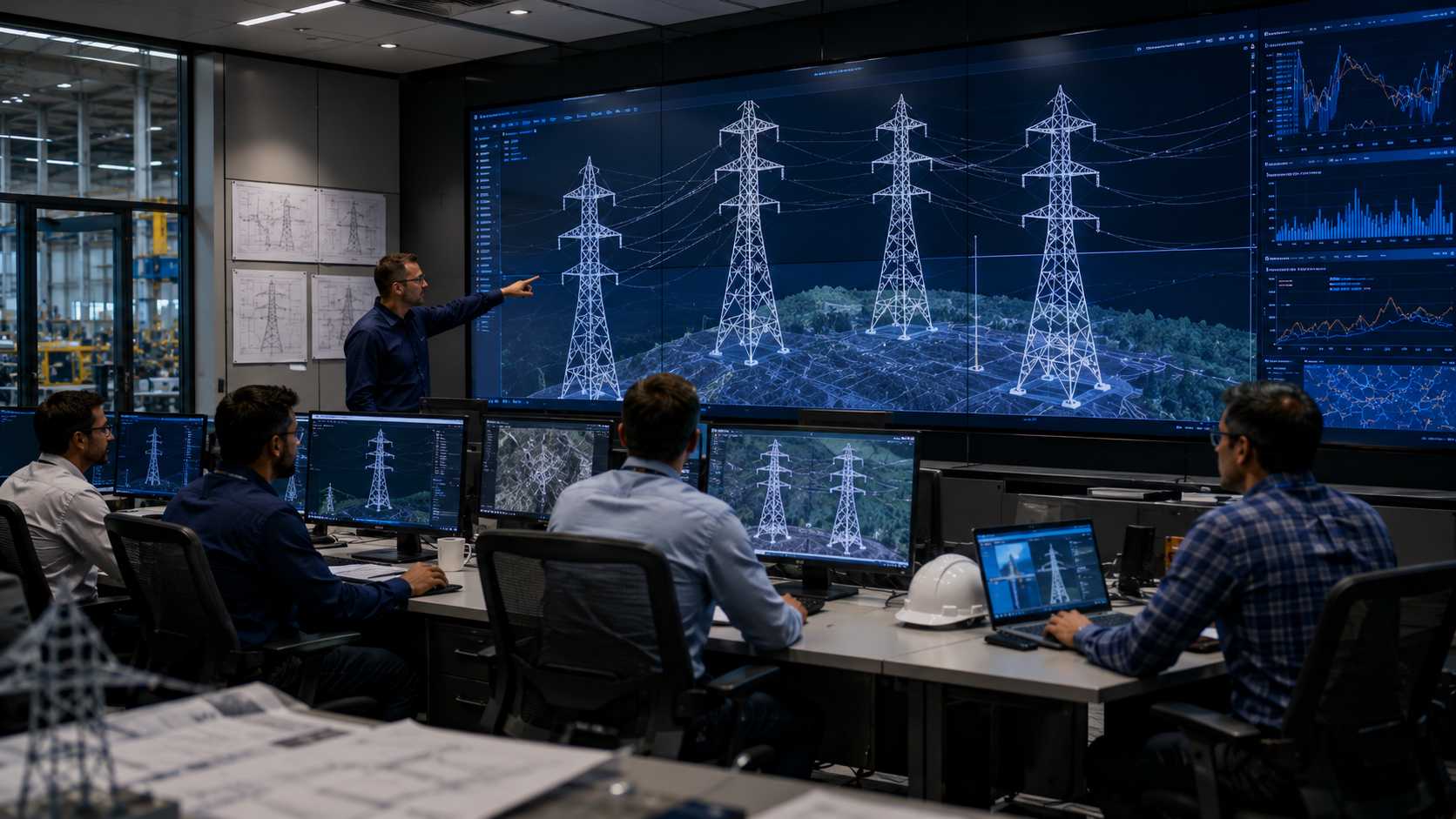
In-house engineering specialists deliver ERS tower design, structural analysis, IEEE 1070 compliance, and advanced PLS-CADD solutions for every project.
Complete in-house manufacturing ensures strict quality control from raw materials to finished ERS tower components with reliable and consistent production.
Flexible ERS rental solutions provide immediate system availability with complete logistics support for utilities and EPC contractors across projects.
Expert installation teams provide tower erection, conductor stringing, commissioning, and complete field support for safe and efficient ERS deployment.

Pre-positioned ERS inventory and dedicated response teams ensure rapid mobilization with round-the-clock engineering support during critical outages.
One trusted partner manages every ERS project stage from engineering and deployment to commissioning, decommissioning, and tower retrieval.
Everything you need to know about HiTech ERS solutions, capabilities, and standards.
Hi-Tech ERS towers are available in five configurations: Suspension (for straight routes), Running Angle (for directional changes), Dead-End/Tension (for high-load termination and crossings), Herringbone (twin-mast multi-circuit), and Chainette (portal-style wide corridor). Each is engineered for a specific functional role within a transmission corridor.
A Suspension configuration supports conductors on straight or near-straight transmission sections where conductor loads are balanced transversely. It is the most common ERS configuration used for emergency bypass lines, reconductoring corridors, and temporary restoration routes along straight alignments.
A Running Angle configuration is used where the transmission line changes direction — at deviation angles typically between 2° and 30°. The cross arm and structure are designed to handle the resultant horizontal conductor load created by the change in line direction, making it suitable for route diversions and corridor adjustments.
A Dead-End or Tension configuration is required wherever the full longitudinal conductor tension must be transferred to the structure — at line terminations, river crossings, long spans, section boundaries, and critical restoration anchor points. These structures are significantly more robust than suspension types and are typically guyed for additional stability.
The Herringbone is a twin-mast ERS arrangement where two vertical masts are connected by cross-bracing in a herringbone pattern. This configuration provides significantly increased structural capacity, making it suitable for multi-circuit systems, heavy-duty restoration projects, and complex loading conditions that exceed the capacity of single-mast configurations.
The Chainette is a portal-style ERS structure designed for wider transmission corridors and special crossing requirements. Its wide base and horizontal top beam allow it to span greater widths than conventional mast configurations, making it the configuration of choice for portal structure replacements and wide corridor crossings.
Yes — in fact, most ERS restoration routes use multiple configurations. A typical route will use Dead-End configurations at each terminal, Suspension configurations across straight sections, and Running Angle configurations wherever the route changes direction. Configuration selection is performed section-by-section based on the engineering requirements at each location.
Configuration selection follows a structured engineering evaluation covering route geometry, tower function, conductor loading, span length, circuit arrangement, voltage level, weather loads, foundation conditions, and access constraints. Hi-Tech's engineering team performs this evaluation for each project to ensure the deployed configuration matches the specific requirements of the transmission corridor.
River crossings require Dead-End/Tension configurations on both banks of the crossing. The dead-end structures anchor the long span conductors across the water body, absorbing the full longitudinal tension generated by the extended span. Suspension towers on either side of the dead-ends carry the normal balanced loads on the approach sections.
Yes. All five Hi-Tech ERS configurations — Suspension, Running Angle, Dead-End/Tension, Herringbone, and Chainette — are available for deployment on systems from 33kV through to 800kV, including 400kV EHV and 765kV UHV corridors. Configuration dimensions, structural capacities, and insulator string arrangements are engineered to suit the specific voltage class requirements.